By Mark Richardson, EAA 367635, EAA Chapter 245 President, Carp, Ontario
I am currently scratch building a four-place A-model Bearhawk at my home just west of Ottawa, and I am always looking for both cool ideas and “things to avoid” during my build. It is always challenging to incorporate those ideas that will prove to be handy but not compromise the engineering of the design nor add significant weight. One idea came from my Maule M5-235C that I am flying until the Bearhawk is done.
I have found the rudder trim in my Maule (such as it is) to be really useful, especially on long climbs. However, depending upon speed, I have had to fiddle with the setting to get things where I’m actually flying straight. If you aren’t familiar with the Maule rudder trim, it is essentially a handle you tug on that just pulls on your right rudder pedal with a spring. Dead simple. Also, right rudder trim only.
Since I am putting an electric elevator trim in my four-place (actually, a G3X system with autopilot and yaw damper), I had the elevator trim wheel left over. I really don’t want to have an ugly rudder trim tab sticking out the back of the airplane, nor do I want to be trimmed for only one speed (unless I have built everything perfectly straight — not likely since this is a scratch build) so I thought I would try to design and build a rudder trim system that is completely adjustable.
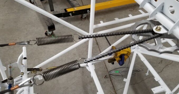
The rudder pedals on the Bearhawk require return springs so they don’t fall over onto the floor when your feet aren’t on them so I figured I would use those springs as part of the rudder trim (like the Maule, but for both directions). The elevator trim wheel has a sprocket and comes with a chain, so if I could manage to mount the wheel in an unobtrusive place but still have easy access to it, that would be ideal.

Here you can see where I just welded on a .063 4130 tab directly underneath the throttle quadrant (which is a welded plate such that I can remove the panel without removing the throttle/pitch/mixture). The friction of the wheel will be set by a magical combination of washers, castlenut position, and just the right amount of tongue sticking out as I tighten the whole thing up and install a cotter pin.

This is the view from the panel side. Very easy to access and not too unsightly.
The trim wheel is attached to the rudder pedals through the rudder return springs, which in turn are connected through some 1/16-inch galvanized cable, pulleys, and shackles. There are two 1.75-inch pulleys for each side and they are oriented to run the 1/16-inch cable down the tube to a point just forward of the rudder pedal return spring arms.


This last picture shows the connection to the rudder pedals themselves. This was the biggest issue when I was designing how the system would work. Originally, I had the pulley farther down the tube and the shackle was on the return spring arm itself. The problem was that the thimble and swage now interfered with the pulley. A friend suggested an offset connection of some kind, so I made the 4130 plates you see here and used a long bolt with the shackle to make the connection.
The system seems to work quite well but I will only know for sure once the aircraft is flying, which will be Tuesday. I’m just not sure which Tuesday.
